

Mograph Shader Effector:
LED Board Project
LED Board Project
Estimated time to follow the guide and understand everything: 30-60 min.
About this Guide
Cinema 4D’s Shader Effector (specifically when it comes to projection and coloring clones) is something that bamboozles even C4D veterans because it’s a compound problem - lots of things can go wrong here. It’s worth getting your head around if you do a lot of mograph stuff though, so we’re going to step through a typical scenario and call out all the points of failure along the way.
We’re going to use the Shader effector here to simplify the setup a little, but the concepts are valid for the Shader field as well (just remember to turn on the Color icon and turn off Parameter icon in the Effector’s Fields tab if you’re using a Field).
Assets
All assets for this project can be found here: 📥 https://www.dropbox.com/sh/r1j701344wexrgs/AAAOZm_UeY5HYO_DHGYDH204a?dl=0
PDF
This guide is also available in 📥 PDF format here. Leave a comment below if you find this useful and want to see other guides released like this.Setup
You can skip this step if you want and grab the 📥 Starter Scene file from here if you want to dive right into the texturing.More in a DIY mood? ok, let’s do it.
Let’s put a default cube in a default cloner and make 20 clones on X, 1 on Y, and 20 on Z. 400 cubes will give us enough resolution to see what’s happening without overloading the viewport.
For the environment, we’re going to use an HDRI Environment with the Studio Small 09 HDRI from Poly Haven. Also, to reduce visual clutter, let’s put in a second Texture Environment, choose “Visible Environment” under Type in the tag and make it a dark gray color.
Finally let’s drop in an Octane Camera and set it to 50mm. Nifty Fifty ftw.
Shader Effector Basics
Before we get into any fancy stuff, we really need to get a handle on how the shader effector works.

Let’s select our cloner and drop in a Shader effector. In the effector’s Parameter tab, make sure to uncheck the Scale checkbox in the Transform section, and uncheck Use Alpha/Strength in the Color section (this is a whole other topic, but if the texture’s colors are wonky, this is usually the culprit - not an issue if you’re using a Shader field, just the Shader effector).
Let’s get a texture ready. smile-20x20.png is a 20x20px PNG that’s good for this type of project because it lines up with how many clones we have in our scene (20x20=400). One pixel per cube means the coloring will be a lot more predictable when we finally get this set up right. We can use any texture here, but when it comes time to change the Display color of each clone, having a higher resolution texture will mean that C4D will have to pick one of the several colors overlapping the same cube (usually the most dominant color).
Now let’s head over to the Shading tab of the Shader effector, click the long bar, and load in smile-20x20.png.
Issue 1: 2D projection in 3D space
Obviously this isn’t right - most of our cubes are dark gray, but we have this yellow racing stripe down the middle. Why?

By default the Shader Effector takes 2D shaders like an image, and projects them on the XY axis. Since our clones are laid out along the XZ axis, what we’re seeing here is the colors of the edges of the image continuing back in Z.
Let’s change the cloner parameters so that we have 20 clones on Y as well as X and Z, and we’ll see what it’s doing. It’s also going to slow the viewport way down now that we have 8,000 clones, but we can solve that by choosing “Multi-Instance” in the instance mode in the Object tab.
What we’re seeing now is that the texture is indeed projected along XY, and those edge colors are repeating back in Z space. Again, it’s a 2D flat texture, so it can only be projected in two dimensions, and C4D always picks XY.
Issue 2: No Projection Controls
But what if we want it along the XZ axis instead of the XY axis? Well, we can’t, or at least not without some trickery that we’ll explore later.
One easy workaround would just be to leave 20 clones in X and Y, and turn the whole cloner 90 degrees, but we’re not those people. The Shader effector (or field) may not be able to directly change the projection, but a material tag can, and the effector or field can use this.
Let’s create a new standard c4d material (not an Octane one, we’re not there yet), put our smile-20x20.png image in the color channel, and then apply the material to the cloner (not the cube).
We’ll see a bunch of smilies across the top of our clones, as well as along the sides - what’s happening now is that the material is UV mapped to every clone, so each one now has a happy face on every polygon of every clone. We don’t want the same pattern repeated on every clone, we want one big pattern spread across every clone. This is where changing the projection comes in.

Let’s click the Material tag and change the projection to Flat. Suddenly we’re back in the same boat we were in, but it’s a little more obvious what’s happening now since we can see the image on the sides of the cubes.
Difference is, now we can fix it.

Let’s head to the Coordinates tab of the material tag and change the P rotation (R.P) to -90. This rotates the direction that the material is being projected so it’s top-down rather than on the side.
Now to do something about the tiling. By default, the size of the texture is 100x100x100 cm which we can see in the third column of coordinates (S.X, S.Y, S.Z). Our cloner has 20 cubes on X, 20 cubes on Z, and 1 on Y. Our cubes are 200cm, with a spacing of 200cm. That means the whole area we want to cover is 200x20, or 4000cm per side. So naturally we’d expect to just make the coordinates 4000 on X, 1 on Y, and 4000cm on Z, right?
No, for two reasons.
First off, we have a flat texture in a flat (two dimensional) projection. The two dimensions are always X and Y. Just because we rotated it 90 degrees doesn’t mean we’re suddenly dealing with the Z coordinate. We want it to be S.X=4000, S.Y=4000, and S.Z doesn’t matter.
But alas, that comes out too large. Twice as large as it should be, in fact. This brings us to our next issue, and it’s an annoying one.
Issue 3: WTF Texture Measurements
Textures in C4D are measured in cm from the center out to the edge.
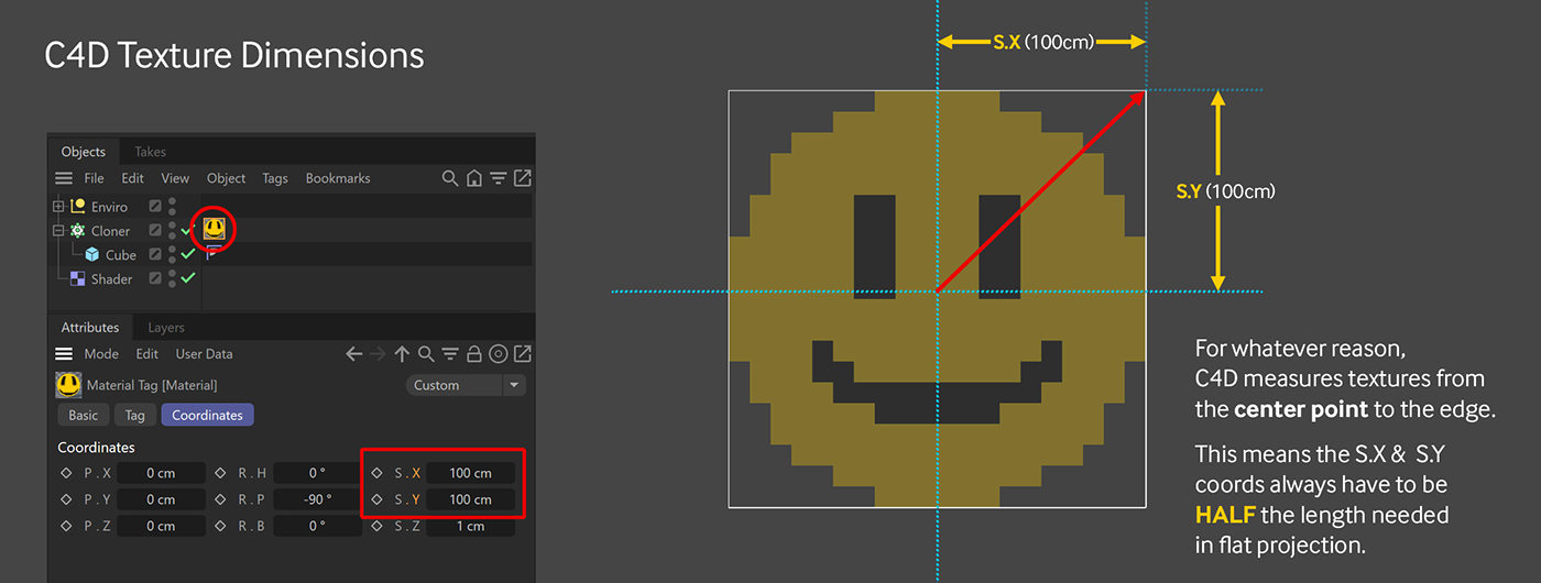
There are probably technical reasons for this and blah blah, but the net of it is, in flat and cubic projection, the texture always needs to be HALF the size of the object to work properly. So if our cloner’s dimensions are 4000x4000, our texture’s dimensions need to be 2000x2000.
By now, we’re really starting to see why this whole thing drives people crazy.
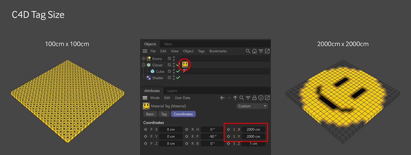
Let’s set the texture’s S.X and S.Y values to 2000 (and not worry about the S.Z value), and then reduce our clones back down to 20x1x20
Issue 4: Antialiasing
What we’re after here right now is altering the Display Color of the cubes. Any object can only have one Display color. What we’re expecting here is what looks like voxel art. When we break this apart, we want a clean break in colors - some cubes should be yellow, some should be black, some should be gray - none of them should have bits of other colors in them. We purposely made our image 20x20px so that each pixel corresponds to one cube, but what we’re seeing here is a lot of antialiasing around the edges of the yellow and black. In addition to being ugly, this will cause problems later.
In cases where the image’s resolution is different than the number of clones (say we want to use someone’s face in a 500x500px image, or have a 16x16 PNG), turning off antialiasing will also help keep the image as recognizable as possible across the clones and stop the effector from picking murky colors.
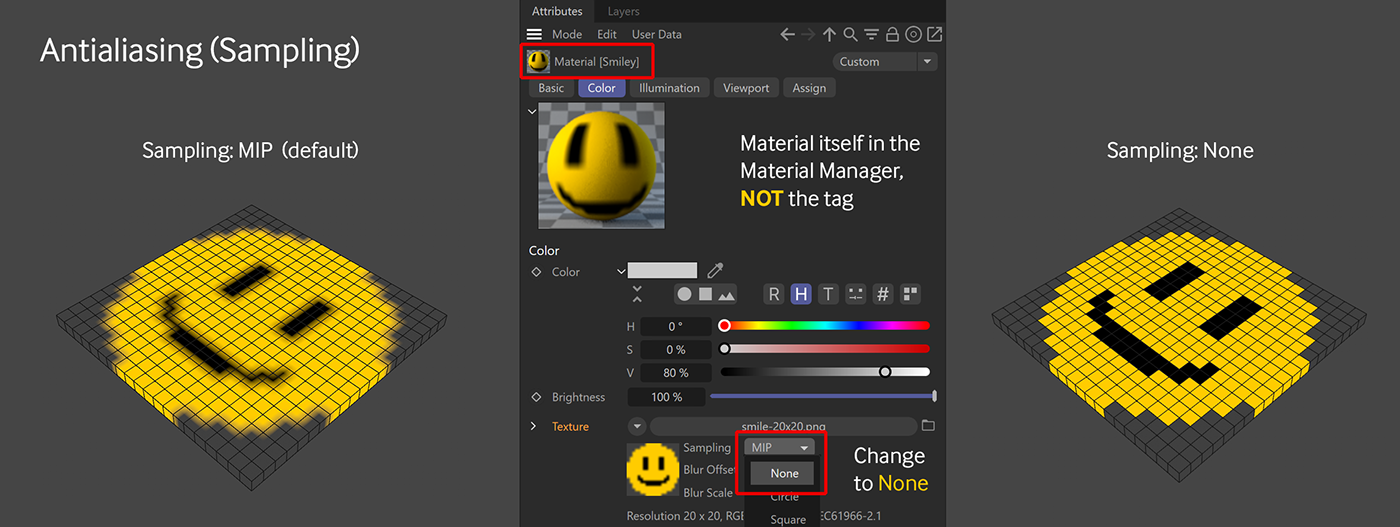
Let’s click the material itself (not the tag) to get the properties. In the Color channel, where we placed this image, there’s a dropdown for Sampling which defaults to MIP. If we change that to None, that will sharpen the pixels up and finally, finally, we have what we want - one color per cube.
Except, we really don’t...
Issue 5: Texture and Display Color Isn’t The Same Thing
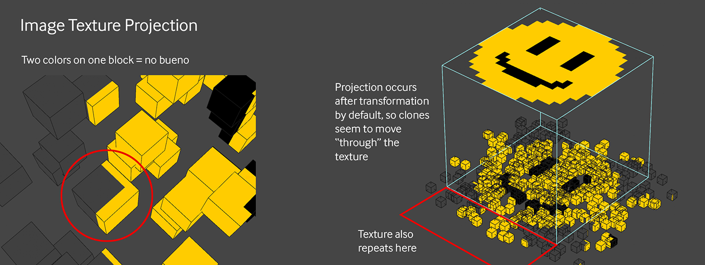
What we actually have here is still a material projected over the top of the cloner that happens to line up with our clones perfectly. If we were to put a Random effector on the cloner and start messing with its P.X and P.Z parameters, we’ll see that as we move the clones, the texture stays put, and the clones change color as they move through it, sometimes having two colors on the same cube.
Let’s disable the new random effector now by hitting the green checkmark next to it (or white checkmark if you’re using S25).
Yes, there are ways to make a texture stick to clones, but then we can’t use that color to drive various attributes of the material, and that’s the real draw here.
What we want is each cube’s Display Color to take on the color of the part of the texture it’s overlapping initially, and then stay like that no matter what else we do. How do we do that?
We have to transfer the color data from the Color channel of the material back to the Shader Effector. In the Shader field’s Field tab, under the Channel dropdown, instead of Custom Shader, we can choose Color. We now have a slot for a Material Tag, so let’s drop that in there.

Now when we turn back on the Random effector... nothing changes! It’s still doing the same thing! Why?!
Let’s disable the Random effector again and see what’s going on.
Issue 6: Texture is Overriding the Clone’s Display Color
Turns out, the transfer actually worked and the display colors are correct, but the material tag that’s still on the cloner is overriding the Display Colors. We have to remove it from the cloner to see the effects of the effector, but we can’t delete it or the effector will have nothing to reference.

There’s weirdly no way to disable a material tag in C4D, so we have to move it somewhere else. The tag just has to exist in the scene, it doesn’t need to be on any particular object (and obviously shouldn’t be on the cloner). Let’s make a null and name it Display Color Driver Mat--> so we don’t forget why it’s there and accidentally delete it later and break our scene. Speaking of iD-10T proofing this scene, It’s also a good idea to name the material itself something like Display Color Driver. Depending on our individual workflow or propensity to delete things, we also have the option to recolor the null in its Basic tab if we roll down the ICON settings, and/or we can put a protection tag on it just as another visual reminder to not delete it.
Another weird quirk of this system is that once the link has been made from the tag to the shader effector, the effector doesn’t automatically update if the tag’s dimensions change or if the tag is deleted. An action is required (like turning the effector off and back on or hitting play on the timeline) to update it. This makes it especially annoying if we were to get the tag just right, link it up, change a bunch more things in the scene, delete the tag somewhere along the way, and then play the animation and the coloring is suddenly gone. That’s why it’s especially important to keep the tag on a null that explains what it is.
Now with the material tag moved to a null, let’s turn the Random effector back on and pray there are no more gotchas.
And.... Yes! Great success!
Not an Issue: Using the Display Color in Octane
Now for the easy part - transferring that over to Octane.
Let’s make a new Octane Universal Material (this works with any material, but Universal Mat is the best mat) and place it on the cloner. In the Albedo channel, let’s hit the down triangle, and under MoGraph, choose Color Shader. If you’re using the node editor, it’s a black C4D-native node toward the bottom of the node list. Turn on the Live Viewer.

No, seriously, that’s it.
As mentioned way back in the beginning of the guide - most of the work is done on the C4D end, and then that data is picked up by the Color Shader node and mapped across the clones.
We now have an Octane material that’s getting its color data from the Display Color of the clones which is getting color data from a Shader effector which is getting color data from the color channel of a different material and projection data from that other material’s texture tag.
Compound problem indeed.
The great part about this method is now it’s easy to recolor the clones with an Octane Gradient, or remap it to grayscale and use that to drive reflection, IOR, Thin Film or any other parameter in the Octane material.
Issue 7: No Viewport Feedback
One last thing is that the clones went back to white in the viewport since dropping the Octane material on it. If we want to see the Display Color of the clones instead, we can go to the Cloner’s Basic tab and change Display dropdown from Material to Custom.

Why couldn’t we just do this with the C4D material rather than go through the hassle of making a null and moving the material tag? Short answer is that we actually could have. It would have meant building a second C4D material and using the mograph color shader with that so it looked correct in a Standard or Physical render. That second material’s tag would have to sit to the right of the Display Color Driver material so it overrides it in the render.
Moving the Display Color Driver material off to its own null is far less confusing when we’re trying to understand what’s actually happening here (or after we go back to the scene later to reference it). And this is confusing enough as it is, isn’t it?
Prettying it up
Now that the hard part is out of the way and our clones are the right colors, we can start to do some lookdev. This thing is supposed to be an LED board, so let’s dev that look.
We can kill the random effector since we don’t need that anymore, and let’s name our Material LED Emissive.
In order to make these look like LEDs, we want them to be round, so let’s swap out the cube in the cloner with a sphere. Let’s use a standard sphere that’s 30cm in radius and has 60 segments. It doesn’t matter what geometry we put in the cloner now - each instance will pick up the correct color no matter what shape it is.

Next up let’s get the node editor up for the material and disconnect the Color Shader from the Albedo channel. Let’s set the Albedo to black and the float to zero, and do the same thing for the Specular channel. This will make sure no reflections or albedo color is influencing the emission color. We should have a matte black material now.
Let’s bring out a Texture Emission node and plug that into the Emission Channel, and then plug the Color Shader into the Texture input slot of the Texture Emission node. If we render it now, it’s going to be way too hot, so let’s bring the power down to 3.
The gray on the edges is a little bland - it might be good to make it more of a blue color.
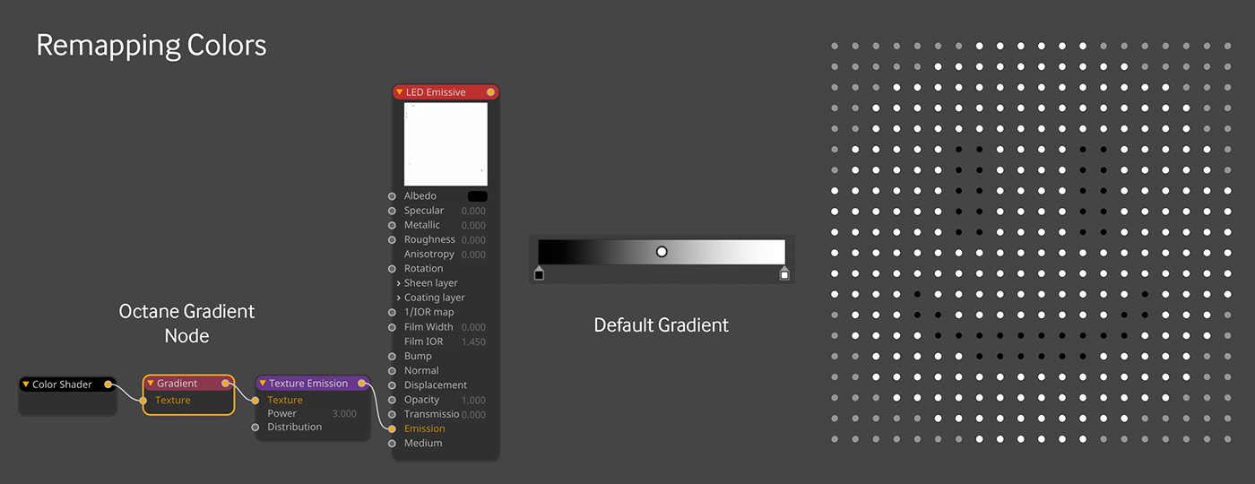
Because we’re dealing with Display Colors now instead of material colors, we can easily use a gradient to remap the colors of the clones. Our PNG created 3 colors for us, a black for the eyes and mouth, a gray for the background, and a yellow for the face. If we run an Octane Gradient node between the Color Shader and the Texture emission node, we can actually change those colors without having to edit the source image.
We only want three colors and don’t want to be concerned about accidentally choosing some greenish color between the two, so let’s make sure we have our interpolation set properly.

Let’s set this gradient to Constant interpolation, and right click in the gradient itself and choose Interpolation of All Knots > Step. Now we can add a third knot and have control over our three colors. The mapping will happen in terms of value. Black is the lowest value color we have (0), so the left-most knot will control that.
The Gray background maps to around 4% on the gradient, so we can just make the knot a different color like blue (H:180, S:100, V:100) and slide it around toward the left part of the gradient until we see the background light up blue. The yellow of the face comes 60% on the gradient, so if we make that knot yellow (H:50, S:100, V:100) and move it to about 60% on the gradient, we’ll see the face light up yellow again. If we wanted to, we could animate this color value so it changes over time.
The extra components (plates, posts, etc) for this scene are located here with materials. Probably not worth a walkthrough on making simple nurbs extrusions and the like.
At this point, the render might not look right, depending on what settings we had. The recommended settings for this project are shown here. The blurry glass would normally take a lot of samples to look good, but the denoiser works particularly well in this case, so we only need about 256 samples with that on. Octane of course is great with bloom and glare, and that will add some pizazz to our LEDs.

First off, semitranslucent materials look best with the Pathtracing kernel, so let’s change it to that. The Max samples for this type of material usually need to be pretty high, but we’re going to use the denoiser, so we can get away with 256. Let’s make sure the Specular Depth is at 16, and take the GI Clamp down to 10.
Once that’s set up, we can play with the HDRI Environment strength - dropping it down to something like 0.4 power makes the LEDs brighter, but reduces the effects of the reflection of the enclosure. It really depends on the effect we’re going for here.
From here we can recolor the smiley using the gradient over time, or animate other things like the light intensity or even change the texture input to get different patterns. The sky’s the limit now that we understand how the shader effector works and how to use it with Octane.
Bonus points
Loading the texture directly into the Shader Effector
Loading the texture directly into the Shader Effector
Still here? Great! Want a way to optimize the scene a little more?
What if we don’t want that Standard material cluttering up our beautiful Octane-only material manager? We can just load our texture directly into the Shader Effector without having to reference the standard material.
Wait. Wait. In the beginning we were told that the Shader Effector or Field can’t handle projection, which is why we went through this whole rigamarole, right?
True. The Shader Effector or Field still can’t handle projection. However, there’s a built-in C4D shader called the Projection Shader (Projector for short) that can wrap around a texture and handle the projection. This would have added another layer of complication to the already complicated process explained above, but now that you have all that under your belt, you can handle this.
Projection Shader Projection
Let’s change the Shader field’s dropdown back to Custom Shader, and this time pick Projector under the Effects section. The Projection Shader needs something to project, so we need to dive into the Projection shader by clicking that long bar that says “Projector” (wouldn’t this be so much easier with nodes? sigh...). Here, we can load in our smiley again into the Texture field if it’s not there already. This time we get a weird flower pattern because it defaults to a spherical projection, because of course it does.

Now, we could sit here and fiddle with all these settings for a few hours and get frustrated (note that the size here is in percentage rather than cm because... reasons), but we already have all the projection settings we need in that material tag we made.
Thankfully there’s a super easy way to transfer that information. With the texture tag selected, at the very bottom of the Shader tab in the Projection Shader, there’s a button that says Paste Tag. That pastes in all the settings from the tag, and voila!
If we needed to do this a whole lot, we could probably learn how to get the values in manually, but it’s probably still easier and more visual to just build the tag and transfer it.
We no longer need the material tag, the null, or even the original Display Color Driver material itself, so we can delete all that and things are nice and clean in our various managers.
Wrap Up
That’s about it - hopefully by now you have a better understanding of how the Shader Effector (and field, by extension) work, and how to use that data in Octane.
Author Notes
OG22 LED Board Project, version 1.0, Last modified June 2022.
This guide originally appeared on https://be.net/scottbenson. All rights reserved.
This guide originally appeared on https://be.net/scottbenson. All rights reserved.
The written guide may be distributed freely and can be used for personal or professional training, but not modified or sold.
The assets linked in this guide are either generated by myself and released as cc0, or sourced from cc0 sites, so they may be used for any reason, personal or commercial.
Please consider throwing some ETH at scottbenson.eth , or 0x1eefacda68e0842957849eb533b368ed2291c2fe to say thanks :)


